LDR Alarm using Arduino

Light Dependent Resistor (LDR) is a type of resistor that changes its resistance based on the intensity of the light falling on it. Arduino is a microcontroller platform that can be programmed to perform various tasks, including sensing and responding to the environment. In this blog post, we will explore how to build an LDR alarm using Arduino.
Components required:
- Arduino Uno Board
- LDR
- Buzzer
- LED
- Breadboard
- Jumper wires
Circuit Diagram: The circuit diagram of the LDR alarm using Arduino is shown below:
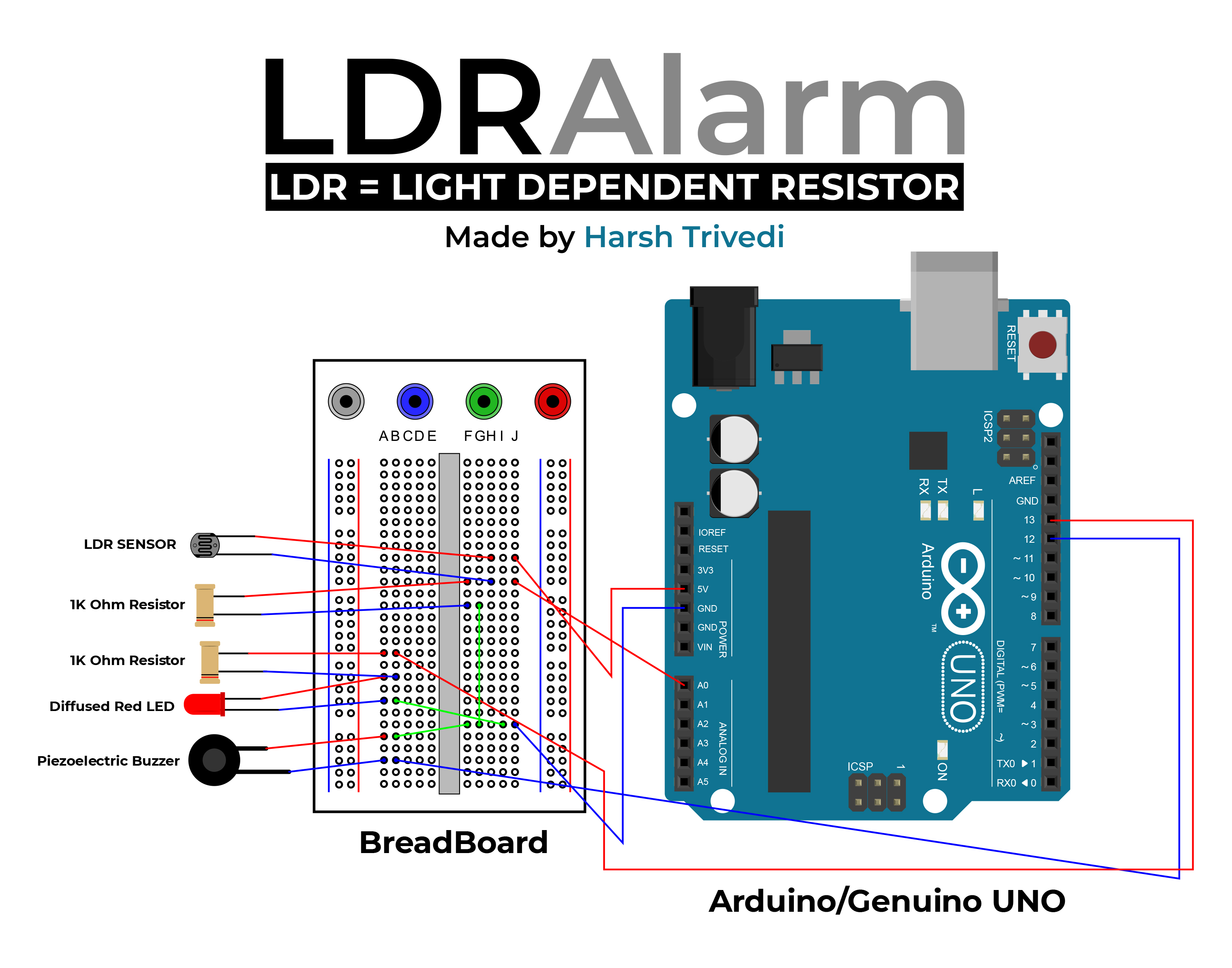
The LDR is connected to the analog pin A0 of the Arduino Uno board. The buzzer and LED are connected to the digital pins 12 and 13 of the Arduino Uno board, respectively. The circuit is powered by the 5V pin of the Arduino Uno board.
Code Explanation:
const int ledPin = 13;
const int buzzerPin = 12;
const int ldrPin = A0;
void setup () {
Serial.begin(9600);
pinMode(ledPin, OUTPUT);
pinMode(buzzerPin, OUTPUT);
pinMode(ldrPin, INPUT);
}
In this section of the code, we define the pin numbers for the LED, buzzer, and LDR. In the setup function, we initialise the serial communication, set the LED and buzzer pins as output pins, and set the LDR pin as an input pin.
void loop() {
int ldrStatus = analogRead(ldrPin);  // Read the State of the LDR value.
if (ldrStatus >= 10) {
tone(buzzerPin, 100);
digitalWrite(ledPin, HIGH);
delay(100);
noTone(buzzerPin);
digitalWrite(ledPin, LOW);
delay(100);
Serial.println(ldrStatus);
}
else {
noTone(buzzerPin);
digitalWrite(ledPin, LOW);
Serial.println(ldrStatus);
}
}
In the loop function, we read the analog value of the LDR using the analogRead() function. If the value of the LDR is greater than or equal to 10, we turn on the buzzer and LED for 100ms using the tone() and digitalWrite() functions. We then turn off the buzzer and LED for another 100ms using the noTone() and digitalWrite() functions. Finally, we print the value of the LDR on the serial monitor using the Serial.println() function. If the value of the LDR is less than 10, we turn off the buzzer and LED and print the value of the LDR on the serial monitor.
Working: The LDR alarm using Arduino works as follows:
- The LDR senses the ambient light level and generates an analog voltage.
- The Arduino reads the analog voltage using the
analogRead()function. - If the value of the LDR is greater than or equal to 10, the Arduino turns on the buzzer and LED for 100ms and then turns them off for another 100ms.
- The Arduino prints the value of the LDR on the serial monitor.
- If the value of the LDR is less than 10, the Arduino turns off the buzzer and LED and prints the value of the LDR on the serial monitor.